Friday, September 30, 2005

Display Oddities

I've been messing with LCD output a bit. At first when I tried to clear the screen, I just ended up with a set of vertical lines, as if it skipped every other pixel in drawing:


So I decided to reinitialize the display. I wrote some bad init code from the start, so i had to mess with it a while, but then I redid it and ended up with blue! even though Its not a color display! I will try to find out if it is a bad thing for the display to have color on it - and whether more colors are possible.

Thursday, September 29, 2005

LCD Accessed

I figured out how to access the LCD today. I read the disassembly for some code that accessed CS1 (where the LCD is hooked up) and found patterns that matched up with those in the LCD user manual. Basically heres how it works:

GPIO1 Bit #3 (8 / -9 when or'd or and'd) corresponds to A0 on the LCD.
The memory address range set in the initialization (which is set simply through MBAR+$8c -> MBAR+%94 if i remember correctly -- look through the original firmware to find it) is used for the data byte.

So it seems for most commands you set A0 to off, set the data byte to the command name, set A0 to on and then set the data bytes to the data you want used by the command).

Since I am familiar with how it works, I should now be able to write an LCD driver and graphics API - though I only need text output so i can write the kernel. I will play around with it a bit first before I write the API though. I'm not really sure how I will design the API yet, as I may want to include bitmap scaling and other things and also may want to have separate application display contexts. I will try to find out quickly if there is a built in mechanism to the LCD for writing characters, as that would make debugging much easier.

Well, here are the lovely pixels I drew:

Wednesday, September 28, 2005

Backlight Flashing Images

Before I work on accessing the lcd display and writing a driver for it, I thought I'd post my work in its current state -- a flashing backlight that litterally looks like a strobe light. Its kinda hard to tell from the pics, but visuals are fun anyways.


The general code for this is as follows:

First you need to initialize the MBAR (Module Base Address Register). Heres my code to do so (with MBAR and MBAR2 already defined):

#if MBAR & 1
#define MBAR_SET MBAR
#else
#define MBAR_SET MBAR+1
#endif

#if MBAR2 & 1
#define MBAR2_SET MBAR2
#else
#define MBAR2_SET MBAR2+1
#endif

move.l #MBAR_SET, %d0
movec.l %d0, %mbar

move.l #MBAR2_SET, %d0
movec.l %d0, %mbar2

Next, you can enable and turn on and off the light with some simple c code:
#define GPIO1_OUT *((int *)(MBAR2 + 0x000000B4))
#define GPIO1_ENABLE *((int *)(MBAR2 + 0x000000B8))

To enable the light:
GPIO1_ENABLE |= 0x00020000;

To turn it on:
GPIO1_OUT &= 0xFFFDFFFF;

To turn it off:
GPIO1_OUT |= 0x00020000;

I am really surprised, because if you set a bit > than the 16th bit in c with binary or, gcc optimizes it to bitset while if its less than 16, it is a binary or with a word. I didn't expect it do be this smart.

Bugs, bugs and more bugs

So, whenever I made any changes to my c code, seemingly unpredictable things would happen. I'll tell you what I learned and the final solution.

At first I thought it may have been a compiler issue. Using -Wa,-m5249 (specifies as should assemble for the m5249 coldfire processor) , I got an error that there was some bad assembly code -- generated code. So it seemed that the compiler was generating bad asm. I tried to do option -m5249 to no avail -- it didn't have that architecture available. I found a very useful list of options if you do m68k-elf-gcc --target-help . -m5200 was kinda-sorta in the list with -m5249 so i tried that and it seems to be working. Hopefully m5249 is a derivative of the m520x architecture.

In this process, I found fomit-frame-pointer to cut down on some assembly which doesn't look to do much. I don't know if I am schedualing my own demise by setting this though.

These didn't fix my troubles, so i ran back to my handy 92 MiB dissassembly and looked through the initialization code. I noticed that the stack pointer was being set to a location on SRAM0 (the 32k one). I tried to set this to that location, but unfortunately used relative addressing. Apparently the instructions look identical except for a # before the symbol name. I noticed the difference by reading the dissassembly of my own code and noticing that some move.l's ended in c while others ended in 9's. Apparently c is absolute and 9 is relative, meaning that bit 3 determines relative / absolute. So after I got the relative / absolute situation worked out, I got it to work.

So I guess the moral is to not setup a stack pointer that will write over your code when its used. I can't believe I could figure this out, because the symptoms were really very random.

I have my code flash the backlight like crazy right now. It is completely seizure-tastic. You really can't look away when it is doing that. I hope to figure out how to get the lcd working soon so I can actually get some decent feedback.

Monday, September 26, 2005

MBARS

I was wrong. It looks like only the pepherials (sp) are set by chip select. Everything else looks to have their own address range setting register ("mask" in the freescale coldfire user manual). The MBAR (Module Base Address Register) and MBAR2 registers set the base address for the SIM (System Integration Module) registers. The SIM is quote

"The SIM provides overall control of the internal and external buses and serves as the interface between the ColdFire core processor and the internal peripherals or external devices."
That sounds like what I'm looking for. So now that I have the MBAR set up, I can access the I2C controlling registers such as the MBCR (MBAR_ADDR + 0x0288 I believe) and other registers.

So i guess the plan is this:
#define the I2C control registers like:
#define MBCR *(MBAR_ADDR + 0x0288)
and then i should (hopefully) be able to access them like so:
MBCR = value;
which gets translated into:
*(MBAR_ADDR + 0x0288) = value;
obviously by the preprocessor.

After I have access to the I2C bus, I will have to try to figure out a way to access the lcd which will be the hard part (not that I none of this was hard)

Chip Selects

After reading through the Coldfire manuals, it looks like the memory addresses like 0x31000000 are mapped by these things called chip selects. Apparently you can set the address range for memory and even peripherals.

The LCD screen is connected to the Coldfire chip via a I2C / GPIO bus. I tried starting the bus as master, but gcc yelled at me because it didn't like me referencing the register by name. There must be some sort of register addressing system perhaps by some base address set up with tthe chip select. If there is one, then it may be possible to set registers via memory address ranges in c. For example, if there is a register a with address A then you could set it simply via *A = value;

So i guess i should figure out how to access the LCD bus properly and then figure out how to interface with the device. I have absolutely no idea how I will be able to test this though. Hopefully I can find a way to get some sort of useful output out of the box soon - otherwise I may have to give up the project because I won't be able to do much more.

Another thing to consider: setting up the chip selects may require supervisor mode. Hopefully the bootloader I'm using didn't take that privelege away.

Friday, September 23, 2005

C Code Only

I figured out a way to load into my main() in c without any assembly using only my linker script. Right now it boots into the firmware using inline asm inside of my main().

Next steps:
  • Find a way to get a form of output. Right now my output has been binary (true / false). If something I'm testing works, it boots into the firmware, otherwise it does nothing. This isn't very helpful in alot of cases. I may consider buying the serial BDM link so that I can get more info, as I will need the cable eventually anyways.
  • Write the kernel. This will likely be time consuming, much more so if I can't get meaningful output from the box.
Related to the kernel, there are two issues that I need to figure out how to resolve:
  • I need to be able to run a thread for a set number of instructions in user mode and get back to supervisor mode afterwards. I need it to jump back to my supervisor instructions if an exception is raised.
  • I need to find a way for a thread in user mode to interact with supervisor instructions. For example, from what I read it looks like LCD drawing, button presses, and basically every other type of IO needs to be done in supervisor mode. So if I have user mode threads, they need to be able to access these functionalities.
So I have a lot of work ahead of myself. I will try to find out the best way to post files to my blog. I really don't have a good network setup so running a server at my home is unrealistic.

First Running Code

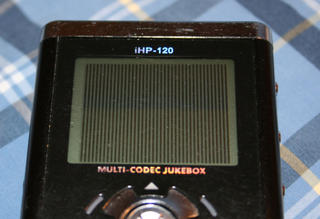
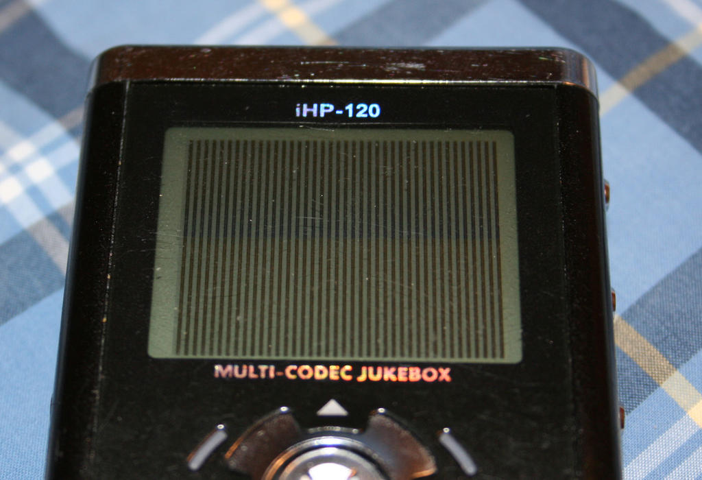
After four days of wrestling with the bootloader and figuring out how it loads code. I got code to run through the Rockbox bootloader! Right now i just am using some assembly that loads the regular iriver firmware on boot. So if it works, the firmware loads. If it fails, it freezes and a paper clip is needed to reset it.

The bootloader loading mechanism is actually rather simple when you figure it out. I had to deal with linker scripts that wouldn't do what I want and frequent disassembling and hex editing to get it to work. I will describe it because it hasn't been documented anywhere else.

The general file structure of your code needs to look like this if you want it to run:
[4 bytes (chksum)][4 bytes(model name)][4 bytes("end of stack")][4 bytes(address of starting instruction)][many bytes(actual code)]
The chksum is computed by adding every byte from the "end of stack" byte onwards to a long.

This code is loaded into memory at 0x31000000 (first memory location of SDRAM), so all of your references to variables and symbols need to be setup so that is the base address instead of 0x00000000. This can be done with a linker script (an lds file).

I'm going to try to figure out if its possible to cut out the assembly altogether in the linking process -- whether it is necessary to have some assembly in order to start code with the bootloader or if it can be skipped. I hope to be able to clean it up a bit tonite and have a simple version up, but my sister is being a pain and not letting me use what is currently our only Windows box to copy code onto the player (for whatever reason Ubuntu Breezy won't let me put stuff on the player -- and Vista build 5219 isn't dual boot friendly)

The tool chain I'm using consists of binutils and gcc, compiled with --target=m68k-elf

Project Introduction

GOALS:
  • To create a functional operating system and application platform for the iRiver iHP-120 (H120) MP3 Player.
  • To learn more about system architecture and operating system fundamentals
  • The develop skills in reverse engineering
PLAN:
  1. Develop an operating system for the iHP-120, using the Rockbox bootloader
  2. Purchase a BDM debugger (it costs $150 which is why i am hesitant to make the firmware before the OS) and create my own bootloader and firmware
  3. Develop applications for the OS and create a usable interface
  4. Create a pretty website for future work